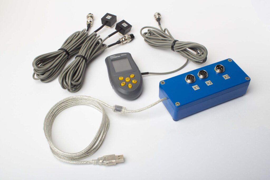
Everything a field engineer needs to balance rotors on-site — from the physics of unbalance to the final verification measurement. Seven-step procedure, trial weight formulas, correction angle measurement, and ISO tolerance tables.
What Is Dynamic Balancing?
Definition: Dynamic balancing is the process of measuring and correcting the uneven mass distribution of a rotating body (rotor) while it spins at operating speed. Unlike static balancing, which corrects mass offset in a single plane, dynamic balancing addresses imbalance in two or more planes simultaneously, reducing both the rotating centrifugal force and the rocking couple that cause bearing vibration.
Every rotating part — from a 200 kg mulcher rotor to a 5 g dental drill spindle — has some residual unbalance. Manufacturing tolerances, material inconsistencies, corrosion, and accumulated deposits shift the mass center away from the geometric rotation axis. The result is a centrifugal force that grows with the square of speed: double the RPM and the force quadruples.
A rotor spinning at 3,000 RPM with just 10 g of unbalance at a 150 mm radius generates roughly 150 N of rotating force — enough to destroy bearings in weeks. Dynamic balancing reduces this force to a level specified by international standards (ISO 21940-11:2016, formerly ISO 1940-1), extending bearing life from months to years and cutting vibration-related downtime.
Why it matters: unbalance is one of the most common causes of vibration complaints on rotating machinery, and it is also among the easiest to fix on-site — a trained technician with the right instrument finishes in 30–45 minutes without removing the rotor.
Static vs Dynamic Balance
Static Balance (single plane)
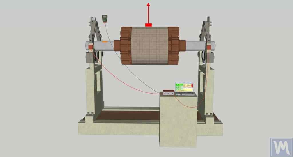
The rotor’s center of gravity is offset from the rotation axis in one plane. When placed on knife-edge supports, the heavy side rolls to the bottom — you can detect this without spinning.
Correction: add or remove mass at a single angular position opposite the heavy spot. One correction plane is enough.
Applies to: narrow disc-shaped parts where diameter > 7× width — flywheels, grinding wheels, single-disc impellers, saw blades, brake discs.
Dynamic Balance (two planes)
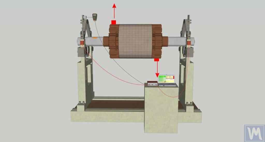
Two (or more) mass offsets sit in different planes along the rotor length. They may cancel each other statically — the rotor sits still on knife-edges — but create a rocking couple when spinning. This couple cannot be detected or corrected without rotation.
Correction: two compensating weights in two separate planes. The instrument calculates mass and angle for each plane from the influence coefficient matrix.
Applies to: elongated rotors — shafts, fans with wide impellers, mulcher rotors, rollers, multi-stage pump impellers, turbines.
Key distinction: a statically balanced rotor can still have severe dynamic imbalance. The forces in one plane exactly oppose those in another, so the rotor does not roll on supports — but the moment it spins, the couple creates violent vibration at the bearings. Two-plane dynamic balancing catches what static methods miss.
Four Types of Unbalance
ISO 21940-2 (the balancing vocabulary, formerly ISO 1925) distinguishes four fundamental unbalance patterns. Understanding which one dominates helps choose the correct balancing strategy.
| Type | Description |
|---|---|
| Static | Single heavy spot. CG displaced parallel to rotation axis. Detectable at rest. Single-plane correction. |
| Couple | Two equal masses 180° apart in different planes. Net force = 0, but creates a torque (couple). Invisible at rest. |
| Quasi-static | Combination of static + couple where principal inertia axis intersects rotation axis at a point other than the CG. |
| Dynamic | General case: principal inertia axis neither intersects nor parallels rotation axis. The most common real-world pattern. Two-plane correction mandatory. |
In practice, almost every rotor you encounter in the field has dynamic unbalance — a combination of force and couple components. That is why two-plane balancing is the default procedure for any rotor that is not a thin disc.
When to Use Single-Plane vs Two-Plane Balancing
The deciding factor is the rotor’s geometry ratio L/D (axial length to outer diameter) combined with its operating speed.
| Criterion | Single-Plane (1 sensor) | Two-Plane (2 sensors) |
|---|---|---|
| L/D ratio | L/D < 0.14 (diameter > 7× width) | L/D ≥ 0.14 |
| Typical parts | Grinding wheel, flywheel, single-disc impeller, pulley, brake disc, saw blade | Fan rotor, mulcher, shaft, roller, multi-stage pump, turbine, crusher |
| Unbalance types corrected | Static only (force) | Static + couple + dynamic (force + moment) |
| Correction planes | 1 | 2 |
| Measurement runs | 2 (Run 0 + Run 1) | 3 (Run 0 + Run 1 and Run 2, one trial per plane) |
| Time on site | 15–20 min | 30–45 min |
Rule of thumb: If the correction planes end up closer together than ⅓ of the rotor’s bearing span, the two planes respond almost identically and the influence-coefficient matrix becomes ill-conditioned — a two-plane solution there is numerically fragile, which is why ⅓ of the span is the practical minimum separation. But if you have a two-channel instrument and can space the planes properly, always use two — it adds 15–25 minutes and catches couple unbalance that single-plane misses.
ISO 21940-11 Balance Quality Grades
ISO 21940-11 (the successor to ISO 1940-1) assigns each class of rotating machinery a balance quality grade G, defined as the maximum permissible velocity of the rotor’s center of gravity in mm/s. The permissible residual specific unbalance eper (in g·mm/kg) is derived from the grade and the operating speed:
e_per = G × 1000 / ω = G × 1000 / (2π × RPM / 60)
- e_per — permissible residual specific unbalance, g·mm/kg
- G — balance quality grade (e.g. 6.3 means 6.3 mm/s)
- ω — angular velocity, rad/s
- RPM — operating speed, rev/min
| Grade | e·ω, mm/s | Machine types |
|---|---|---|
G 0.4 |
0.4 | Gyroscopes, spindles of precision grinding machines |
G 1.0 |
1.0 | Grinding-machine drives, small electric armatures with special requirements; turbocharger rotors are balanced to this level or tighter |
G 2.5 |
2.5 | Gas and steam turbines, rigid turbo-generator rotors, machine-tool drives, turbine-driven pumps, medium and large electric armatures with special requirements |
G 6.3 |
6.3 | Fans, pump impellers, process machinery, flywheels, centrifuges, normal electric armatures, general industrial machinery |
G 16 |
16 | Parts of agricultural machinery, parts of crushing machines, drive shafts (cardan) with special requirements, individual engine components |
G 40 |
40 | Passenger car wheels and rims, wheel sets, drive shafts, crankshaft assemblies (series production) |
G 100 |
100 | Crankshaft drives of fast diesel engines with six or more cylinders; complete car, truck and locomotive engines |
Worked Example: Fan Rotor
A centrifugal fan rotor weighs 80 kg, operates at 1,450 RPM, and the correction radius is 250 mm. Required grade: G 6.3.
e_per = 6.3 × 1000 / (2π × 1450 / 60) = 6300 / 151.8 ≈ 41.5 g·mm/kg
Total permissible unbalance = 41.5 × 80 = 3,320 g·mm. At correction radius 250 mm that is 3320 / 250 = 13.3 g for the whole rotor. ISO 21940-11 splits the tolerance between the correction planes, so a symmetric two-plane rotor may retain about 6.6 g in each plane — the mass of six or seven M6 washers.
The Balanset-1A has this step built in: pick the G grade, enter rotor mass and RPM, and the software returns the permissible residual unbalance in g·mm. It stops there — converting g·mm into grams is your own division by the correction radius, exactly as above.
Related standards: ISO 21940-11 (rigid rotors) and ISO 21940-12 (rotors with flexible behavior) for balance tolerances; ISO 20816-3 (formerly ISO 10816-3) for vibration severity limits.
Seven-Step Field Balancing Procedure
This is the influence coefficient method for two-plane field balancing, applied with a portable instrument such as the Balanset-1A. The same logic works with any two-channel balancing analyzer.
Step 1: Prepare the Rotor & Mount Sensors
Clean bearing housings from dirt and grease — sensors must sit flush on the metal surface. Mount vibration sensor 1 on the bearing housing closest to Plane 1 (usually the drive end). Mount sensor 2 near Plane 2 (non-drive end). Attach reflective tape to the shaft for the laser tachometer. Connect all cables to the measuring unit.
Step 2: Measure Initial Vibration (Run 0)
Start the rotor and bring it to stable operating speed. The instrument measures vibration amplitude (mm/s) and phase angle (°) at both sensors simultaneously. This is the baseline — the "sickness" of the rotor before treatment. Record the values and stop the machine.
Field tip: Wait at least 10–15 seconds after the RPM stabilizes before recording. Thermal transients and air currents settle out in the first few seconds.
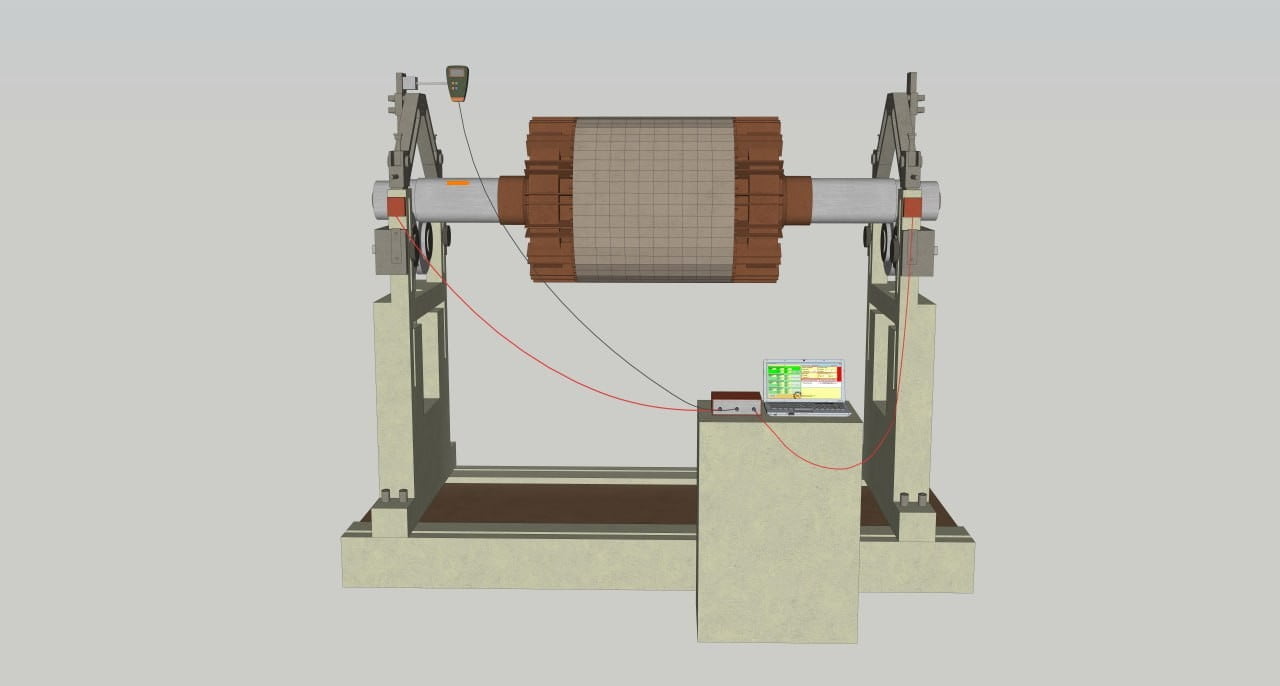
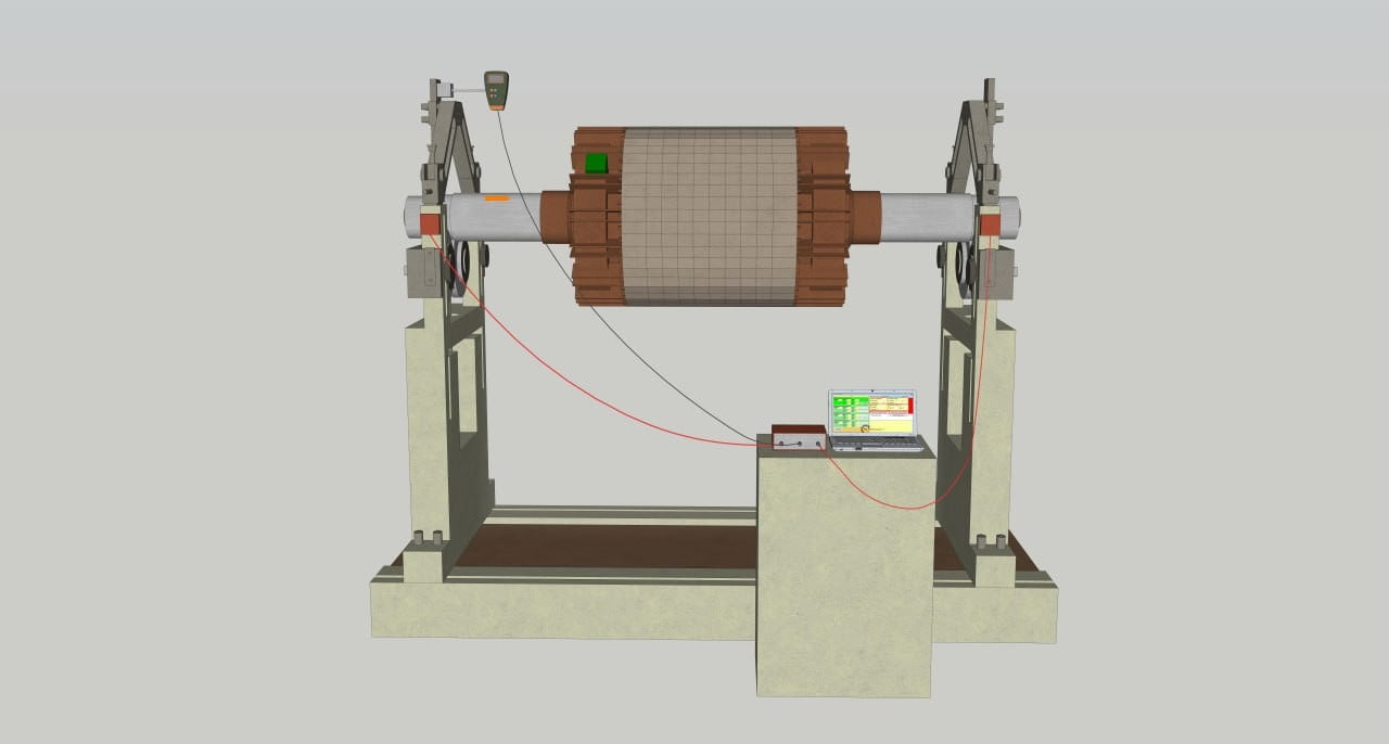
Step 3: Install Trial Weight in Plane 1 (Run 1)
Stop the rotor. Attach a trial weight of known mass at an arbitrary angular position in Plane 1. Mark this position clearly — it becomes your 0° reference for angle measurement later. Restart the rotor and record vibration at both sensors. The instrument now knows how the rotor’s vibration field changes when mass is added in Plane 1.
Field tip: Use a bolt with a washer clamped to the rotor rim, or a hose clamp with a nut for quick attachment. The trial weight should produce a measurable vibration change — at least 20–30% in amplitude or 20–30° in phase at one of the sensors.
How much should the trial weight weigh? Size it by centrifugal force:
m = k × M × g / (R × ω²), where M = rotor mass, R = installation radius, ω = 2π × RPM / 60, and k = 0.05–0.10 (the Balanset-1A uses 0.07). See the Trial Weight Calculation section below for worked examples.
Step 4: Move Trial Weight to Plane 2 (Run 2)
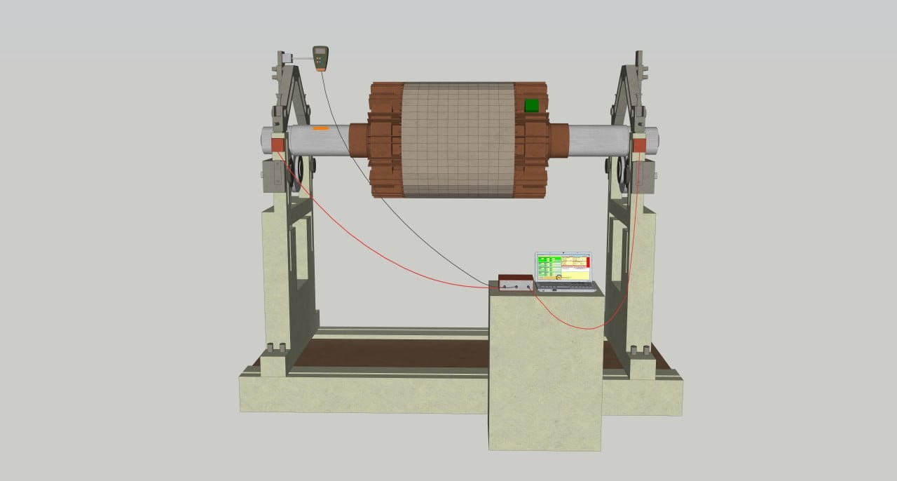
Stop the rotor. Remove the trial weight from Plane 1. Attach the same trial weight (or one of similar known mass) at an arbitrary position in Plane 2. Mark this second reference point. Restart and record vibration at both sensors. Now the instrument has the complete influence coefficient matrix — four complex coefficients linking unbalance in either plane to vibration at either sensor.
Field tip: If you use a different trial weight mass in Plane 2, enter the correct value in the software — the math adjusts automatically.
Step 5: Calculate Correction Weights
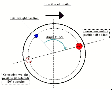
The instrument solves the influence coefficient equations and displays: mass (g) and angle (°) for Plane 1, and mass (g) and angle (°) for Plane 2. The angle is measured from the trial weight position in the direction of rotor rotation.
Do not add your own 180°. If you set the correction method to remove mass (drilling or grinding), the software has already rotated the answer by 180° for you — the displayed angle is where to drill. Turning it a further 180° puts the correction on the wrong side of the rotor and makes the vibration worse.
Step 6: Install Correction Weights
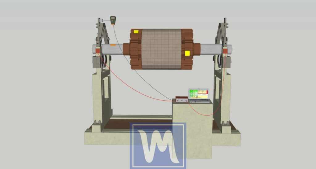
Remove the trial weight from Plane 2. Fabricate or select correction weights matching the calculated masses. Measure the angle from the trial weight reference mark in the direction of rotation. Attach the correction weights firmly — welding, hose clamps, set-screw weights, or bolts depending on the machine type and speed.
Field tip: If you cannot place a weight at the exact angle (e.g. only bolt holes or blade slots available), switch the weight mode from Free to Fixed positions — you enter how many evenly spaced positions the plane has (the two-plane form asks separately for Plane 1 and Plane 2, and the count must be more than 2), and the software splits the correction between the two positions adjacent to the calculated angle.
Step 7: Verify Balance (Run T)
Restart the rotor and re-measure with the corrections installed. In the software this run is Run T — the trim run: it is the verification measurement, and it doubles as the refinement step. Compare the result against the initial baseline and against the vibration-severity limit for your machine class — ISO 20816-3 (formerly ISO 10816-3). If vibration is within specification, you are done. If not, Run T reuses the influence coefficients already in memory to calculate a small additional correction, with no new trial weights.
Note on standards: ISO 21940-11 G-grades are a residual unbalance tolerance in g·mm, not a vibration limit. Use them when you are checking residual unbalance with the balance-tolerance calculator; use ISO 20816-3 when you are judging the mm/s reading.
Field tip: One trim run is usually enough. If you need more than two trims, something has changed between runs — check for loose weights, thermal growth, or speed variation.
Trial Weight Calculation
The trial weight must be heavy enough to produce a noticeable vibration change, but light enough not to overload bearings or create a dangerous condition. Size it by force, not by a percentage of rotor mass: choose a mass whose centrifugal force is a small, fixed fraction k of the rotor’s own weight.
m = k × M × g / (R × ω²) ω = 2π × N / 60
- m — trial weight mass, grams
- M — rotor mass, grams
- k — force fraction, 0.05–0.10 (the Balanset-1A uses 0.07: the value itself on rigid supports, the ceiling on soft ones)
- g — 9,810 mm/s²
- R — trial weight installation radius, mm
- ω — angular velocity, rad/s (N = operating speed, RPM)
Rearranged, k is simply the ratio m·R·ω² / (M·g) — the trial weight’s centrifugal force divided by the rotor’s static weight. Staying inside k = 0.05–0.10 keeps that force at 5–10% of rotor weight, which is safe for the bearings on any rotor that was running before you arrived. Percentage-of-rotor-mass rules of thumb ("1–3% of rotor mass") ignore speed and radius entirely and can be dangerously heavy at high RPM.
Worked Examples (k = 0.07)
| Machine | Rotor mass | RPM | Radius | ω, rad/s | Trial weight |
|---|---|---|---|---|---|
| Mulcher rotor | 120 kg | 2,200 | 300 mm | 230 | ≈ 5 g |
| Industrial fan | 80 kg | 1,450 | 400 mm | 152 | ≈ 6 g |
| Centrifuge drum | 45 kg | 3,000 | 150 mm | 314 | ≈ 2 g |
| Crusher shaft | 250 kg | 900 | 250 mm | 94 | ≈ 77 g |
The Balanset-1A software can do this arithmetic for you, with conditions worth knowing before you rely on it. The window is titled First trial weight estimate, and it exists only in the modern unified balancing form — a fresh install opens the classic balancing form instead, so on a default setup you will not see it. Reaching it means selecting the modern balancing form in Settings, and that option itself appears only with streaming-capable (v5+) firmware. Inside the window you type the rotor mass in kg and the mounting radius in mm by hand: with Run 0 data but no mass and radius you get an angle and no mass, and before Run 0 it returns nothing at all.
What it returns also depends on the support type chosen in that window. On Rigid supports it is the k = 0.07 centrifugal rule above. On Soft supports — the default — it estimates the mass from the measured Run 0 amplitude and uses the centrifugal value only as an upper limit, so the number on screen is often not the k = 0.07 figure.
Different datum — do not mix the two. The angle the estimator suggests is measured from the tachometer mark, and it is valid only when the sensors are mounted coaxially with the tachometer. Every other angle in this guide is measured from the trial weight position. Applying the Step 5 rule to the estimator’s number puts the weight in the wrong place.
Practical tip — verify the response: The formula gives a starting mass that should produce a measurable response. After the trial run, check that the phase shifted by at least 20–30° or the amplitude changed by at least 20–30%. If the response is smaller than that, increase the trial mass and repeat — but stay within k ≤ 0.10, and never let the trial force exceed about 10% of the rotor’s weight. If a legitimate trial weight still produces no response, the vibration is probably not unbalance.
Correction Angle Measurement
The balancing instrument outputs two numbers per plane: mass (how much weight) and angle (where to place it). The angle is always referenced to the trial weight position.
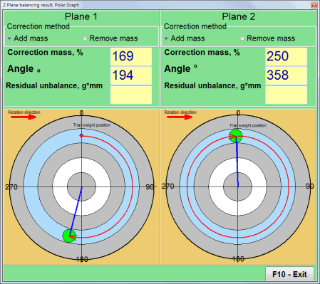
Balanset-1A result screen: the software calculates correction mass and angle for each plane and displays vectors on a polar chart. Red vectors show the required correction; green shows residual vibration after trim run.
How to Measure the Angle
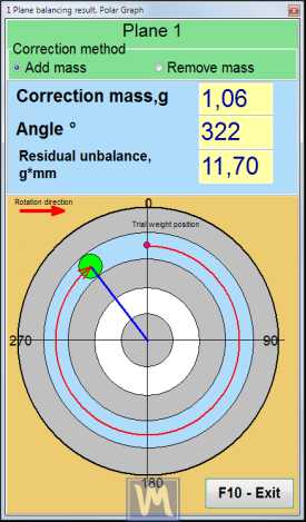
- Reference point (0°): the angular position where you placed the trial weight. Mark it clearly on the rotor before the trial run.
- Measurement direction: always in the direction of rotor rotation.
- Reading the angle: the instrument displays angle f₁ for Plane 1 and f₂ for Plane 2. From the trial weight mark, count that many degrees in the rotation direction — that is where the correction weight goes.
- If removing mass: the displayed angle is already the drilling or grinding position. The software applies the 180° flip itself when the correction method is set to remove mass, so measure to the angle shown and remove material there — do not flip it again.
Weight Splitting to Fixed Positions
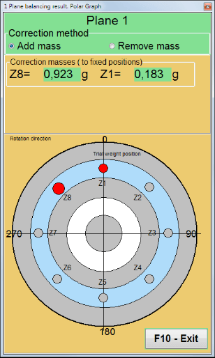
When the rotor has pre-drilled holes or fixed mounting positions (e.g. fan blade bolts), you may not be able to place a weight at the exact calculated angle. The Balanset-1A offers four weight modes — Free, Fixed positions, Circular groove, and Drill. In Fixed positions you enter how many evenly spaced positions the plane has (blades, slots, bolt holes); the software decomposes the single correction vector into two smaller weights at the two positions adjacent to the calculated angle. The combined effect matches the original vector.
Correction Planes & Sensor Placement
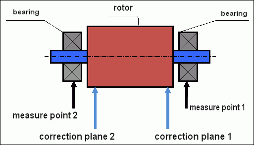
The correction plane is the axial position on the rotor where you add or remove mass. The sensor measures vibration at the nearest bearing. A few key rules:
- Sensor goes on the bearing housing — as close to the bearing centerline as possible, in the radial direction (horizontal preferred).
- Plane 1 corresponds to Sensor 1, Plane 2 to Sensor 2. Keep the numbering consistent or the software will swap correction planes.
- Maximize plane separation: the further apart the two correction planes, the better the couple resolution. Minimum practical separation is ⅓ of the bearing span.
- Choose accessible positions: the correction plane must be a location where you can physically attach weights — a flange edge, bolt circle, rim, or welding surface.
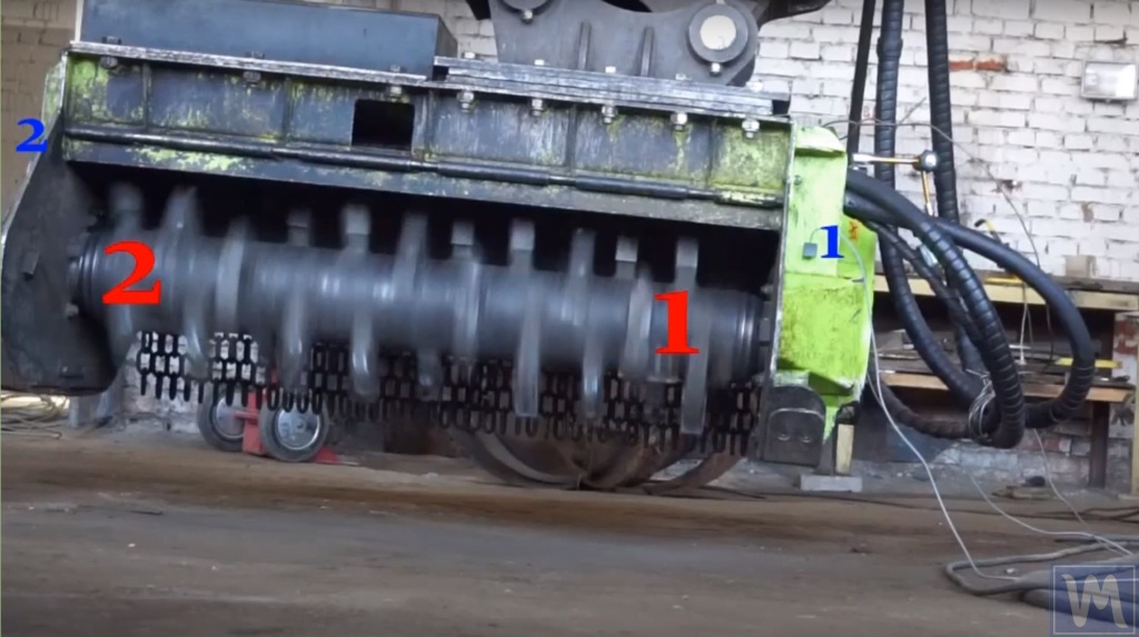
In the photo above, a mulcher rotor is prepared for two-plane balancing. Blue markers 1 and 2 indicate the sensor positions on bearing housings. Red markers 1 and 2 show the correction planes — in this case, the flanged ends of the rotor body where weights will be welded.
Cantilever (Overhung) Rotor
Cantilever rotors — fan impellers, flywheels mounted outboard of the bearing span, pump impellers — require a different sensor and plane layout. Both correction planes are on the same side of the bearings, and sensor placement must account for the overhung mass amplifying couple unbalance.
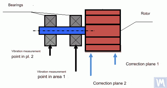
Sensor connection diagram for a cantilever rotor: both correction planes are outboard of the bearing span.
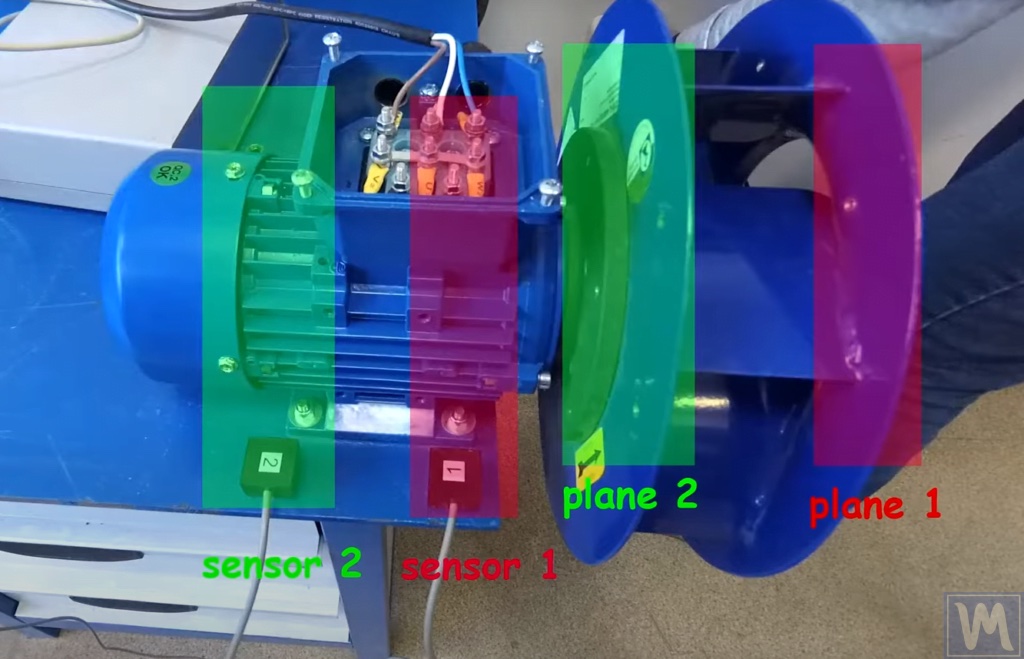
Field example: cantilever rotor with sensor and correction plane positions marked.
Applications by Machine Type
| Machine | Typical specs | Notes |
|---|---|---|
| Industrial fans & blowers | 600–3,600 RPM · G 6.3 · Two-plane | Most common field balancing task. Watch for dust buildup on blades — it shifts balance over time. Re-balance after cleaning or blade replacement. |
| Mulcher & flail mower rotors | 540–2,500 RPM · G 16 · Two-plane | Heavy rotors (80–200 kg) with replaceable flails. Drum speed depends on the drive train — direct PTO-speed drums sit at the low end, belt- or gearbox-driven rotors at the high end, so size the trial weight from the speed you actually measure at the rotor. Unbalance appears after flail wear or replacement. Correct in two planes at the rotor end-flanges. Field result below: 12.4 → 1.4 mm/s. |
| Crushers & hammer mills | 600–1,200 RPM · G 16 · Two-plane | Extremely heavy rotors (200–1,000+ kg). Even here the trial weight stays modest — tens to a few hundred grams by the force rule. Low RPM means large permissible unbalance, but impact loads and bearing cost still justify balancing. |
| Centrifuges | 1,000–10,000 RPM · G 6.3 · Two-plane | Basket or disc centrifuges in food, chemical, and pharma. ISO 21940-11 lists centrifuge drums at G 6.3, but the permissible residual unbalance shrinks in proportion to speed, so at the top of this range the tolerance in grams is very small. Field balancing avoids lengthy disassembly. Check for product buildup inside drum. |
| Electric motors & generators | 750–3,600 RPM · G 6.3, G 2.5 with special requirements · Two-plane | Motor armatures are factory balanced, but re-balancing is needed after winding repair, bearing replacement, or coupling changes. Test with coupling half attached for best results. |
| Combine harvester augers & rotors | 400–1,200 RPM · G 16 · Two-plane | Long augers and threshing rotors pick up soil and crop residue imbalance. Seasonal balancing before harvest prevents bearing failure in the field. Correction weights welded to flights. |
| Pump impellers | 1,450–3,600 RPM · G 6.3 · Single or two-plane | Overhung impellers often need only single-plane correction if narrow. For multi-stage pumps, each impeller is balanced individually on a mandrel before assembly. |
| Turbochargers | 30,000–300,000 RPM · G 1.0 or tighter · Two-plane | ISO 21940-11 does not name turbochargers; G 1.0 or tighter is industry practice for them. Material removal by grinding — no welded weights at these speeds. Above the Balanset-1A’s 90,000 rpm ceiling: this work needs a dedicated high-speed balancing machine, not a field instrument. |
See also the dedicated guides for fan impellers and mulcher and flail rotors.
Weight Attachment Methods
| Method | Attachment | Best for | Limits |
|---|---|---|---|
| Welding | Steel washers or plates tack-welded to rotor rim | Mulchers, crushers, heavy industrial rotors | Permanent. Cannot use on aluminum or stainless without special rod |
| Bolts & nuts | Bolts through pre-drilled holes with locknuts | Fan impellers, flywheels, coupling flanges | Requires existing holes or new drilling |
| Hose clamps | Stainless-steel hose clamp with weight sandwiched | Shafts, rollers, cylindrical rotors in the field | Temporary or semi-permanent. Verify clamp torque |
| Set-screw clip-on | Pre-made clip-on weights (like tire weights) | Fan blades, thin rims, light rotors | Limited mass range. May slip at high RPM |
| Adhesive (epoxy) | Weight glued to surface | Precision rotors, clean environments | Requires clean dry surface. Temperature limit ~120°C |
| Material removal | Drilling or grinding material away from heavy side | Turbochargers, high-speed spindles, impellers | Permanent and precise but irreversible. Use when adding weight is not safe |
Common Mistakes in Field Balancing
| # | Mistake | Consequence | Fix |
|---|---|---|---|
| 1 | Sensor mounted on a guard or cover | Resonance of the cover distorts amplitude and phase readings → wrong correction | Always mount on the bearing housing metal surface |
| 2 | Trial weight too light | Phase and amplitude change is within noise → influence coefficients are unreliable | Ensure at least 20–30% amplitude change or 20–30° phase shift at one of the sensors |
| 3 | Speed variation between runs | Unbalance force grows with RPM² — even a 5% speed change between runs can shift amplitude and phase enough to corrupt the coefficients | Use a tachometer for precise RPM tracking. Wait for speed to stabilize |
| 4 | Forgetting to remove the trial weight | Correction calculation includes trial weight effect → result is meaningless | Follow a strict routine: remove trial weight before installing correction weights |
| 5 | Mixing up Plane 1 and Plane 2 | Correction weights go in the wrong planes → vibration increases | Label sensors and planes clearly. Sensor 1 → Plane 1, Sensor 2 → Plane 2 |
| 6 | Measuring angle opposite to rotation | Correction goes 360° − f instead of f → opposite side of rotor | Confirm rotation direction before starting. Always measure in rotation direction |
| 7 | Thermal growth during runs | Bearing clearance changes between cold start runs → drifting measurements | Either warm up to steady state before Run 0, or complete all runs quickly (<5 min apart) |
| 8 | Using single-plane on a long rotor | Couple unbalance remains uncorrected → vibration may even increase at the far bearing | Use two-plane balancing for any rotor where L/D ≥ 0.14 or plane separation is significant |
Field Report: Mulcher Rotor Balancing
Rotary flail mulcher, agricultural holding in Germany — the full write-up is published as a case study.
| Vibration before | Vibration after | Reduction | Time on site |
|---|---|---|---|
| 12.4 mm/s | 1.4 mm/s | 89% | 40 min |
Machine: PTO-driven knife drum, 180 kg rotor, 540 RPM. After 1,200 hours the front bearing housing showed persistent elevated vibration, and bearing replacements had become a bi-monthly routine.
Setup: Two MEMS vibration sensors on the front and rear bearing housings, optical tachometer on the PTO shaft coupling. Balanset-1A two-plane mode. Sensor mounting: 12 minutes.
Run 0 — reference: front bearing 12.4 mm/s RMS, rear bearing 9.7 mm/s RMS, dominant at 1× with no significant harmonics — mass unbalance confirmed, misalignment and looseness ruled out.
Run 1 — trial weight: 180 g at the 0° reference mark on the front correction plane. The software calculated the influence coefficients and returned correction vectors for both planes.
Correction: front plane 95 g at 147°, rear plane 62 g at 213°.
Verification: front bearing 1.4 mm/s, rear bearing 1.1 mm/s — an 89% reduction on the front bearing, achieved without a trim run.
Two-Plane Dynamic Balancing of a Fan
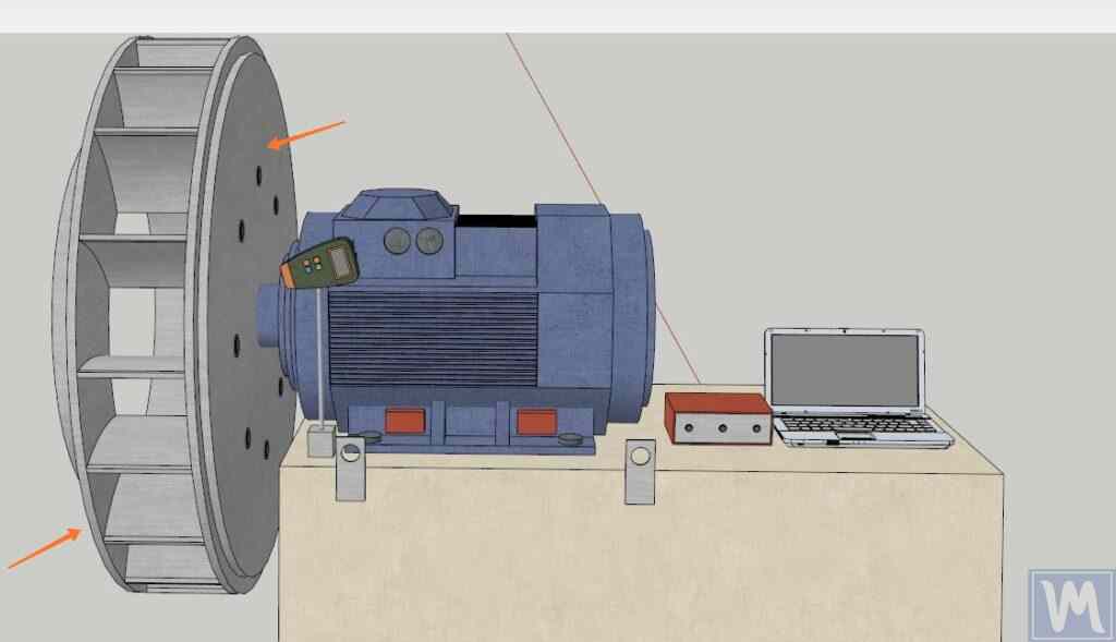
Industrial fans — centrifugal, axial, and mixed-flow — are among the most common rotors balanced in the field. The procedure below walks through a typical two-plane job on a radial fan using the Balanset-1A.
Determining Planes and Installing Sensors
Clean the surfaces for sensor installation from dirt and oil. Sensors must fit snugly to the metal surface of the bearing housing — never mount on covers, guards, or unsupported sheet-metal panels.
Sensor connection and correction plane layout for a cantilever-mounted fan impeller.
Sensor and correction plane positions on a fan rotor: Sensor 1 (red) near front, Sensor 2 (green) near rear.
- Sensor 1 (red): Install closer to the front of the fan (Plane 1 side).
- Sensor 2 (green): Install closer to the rear of the fan (Plane 2 side).
- Plane 1 (red zone): Correction plane on the impeller disc, closer to the front.
- Plane 2 (green zone): Correction plane closer to the back plate or hub.
Connect both vibration sensors and the laser tachometer to the Balanset-1A. Attach reflective tape to the shaft or hub for RPM reference.
Balancing Process
Start the fan and take initial vibration measurements (Run 0). Install a trial weight of known mass on Plane 1 at an arbitrary point, run the fan, and record the vibration change (Run 1). Move the trial weight to Plane 2 at an arbitrary point, run the fan again, and record (Run 2). The Balanset-1A software uses all three measurements to calculate the correction mass and angle for each plane.
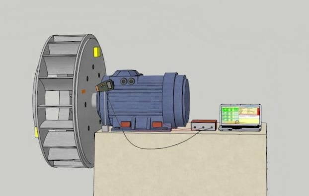
Correction weights installed on the fan impeller at positions calculated by the Balanset-1A.
Angle Measurement for Fan Correction Weights
The angle is measured from the trial weight position in the direction of fan rotation — exactly as described in the Correction Angle Measurement section above. Mark where the trial weight was placed (0° reference), then count the indicated angle along the rotation direction to find the correction weight position.
Balanset-1A two-plane balancing result screen: correction mass and angle displayed for both planes.
Based on the angles and masses calculated by the software, install the correction weights on Plane 1 and Plane 2. Run the fan once more and verify that vibration has dropped to an acceptable level for the machine class under ISO 20816-3. The matching unbalance target for a general-purpose fan is G 6.3 under ISO 21940-11 — a g·mm figure you check with the balance-tolerance calculator, not with the mm/s reading. If residual vibration is still above target, perform one trim run (Run T).
Frequently Asked Questions
What is the difference between static and dynamic balancing?
Static balancing corrects unbalance in a single plane — the rotor’s center of gravity is shifted back to the rotation axis. It works for narrow, disc-shaped parts where diameter is greater than 7 times the width. Dynamic balancing corrects unbalance in two planes simultaneously, addressing both force and couple unbalance. It is required for any elongated rotor where masses are distributed along the shaft length. A rotor can be statically balanced yet dynamically unbalanced — the couple component is invisible until the rotor spins.
How do I calculate the trial weight mass for field balancing?
Size it by centrifugal force: m = k × M × g / (R × ω²), where M is rotor mass in grams, R the installation radius in mm, g = 9,810 mm/s², ω = 2π × RPM / 60, and k = 0.05–0.10 (the Balanset-1A uses 0.07). Because k is the ratio of trial-weight centrifugal force to rotor weight, this keeps the added force at 5–10% of the rotor’s own weight at any speed. Aim for a response of at least 20–30% in amplitude or 20–30° in phase; if the response is smaller, increase the mass but stay within k ≤ 0.10. Avoid percentage-of-rotor-mass rules of thumb — they ignore speed and radius.
When should I use single-plane vs two-plane balancing?
Use single-plane for narrow disc-shaped rotors where diameter exceeds 7 times the axial width — flywheels, grinding wheels, saw blades. Use two-plane for anything longer: shafts, fan impellers, mulcher rotors, rollers, multi-stage pump assemblies. When in doubt, always choose two-plane — it catches couple unbalance that single-plane misses, and only adds one extra measurement run.
What ISO standard covers rotor balancing tolerances?
ISO 21940-11:2016 is the current standard for rigid rotors. It replaced ISO 1940-1:2003. It defines balance quality grades from G 0.4 (gyroscopes) to G 4000 (slow marine diesel crankshafts). Common grades: G 6.3 for fans and pump impellers, G 2.5 for turbines, turbo-generators and machine-tool drives, G 1.0 for grinding-machine drives and small armatures with special requirements (turbocharger rotors are balanced to that level or tighter), G 16 for parts of agricultural machinery and crushing machines. The grade is the maximum permissible velocity of the center of gravity in mm/s: G = e_per × ω. Divide the grade by the angular velocity to get the permissible specific unbalance e_per, then multiply by rotor mass and divide by the correction radius to get the allowable residual mass.
How do I measure the angle for correction weight placement?
The instrument calculates the correction angle relative to the trial weight position. Mark where you placed the trial weight — this is your 0° reference. Then measure the indicated angle in the direction of rotor rotation from that reference point. The correction weight goes at the resulting position. If you are removing mass instead of adding it, do not flip the angle yourself — with the correction method set to remove mass the software has already applied the 180°, so drill or grind at the angle it displays. Use a protractor or divide the circumference into marked segments before starting.
Can I balance a rotor without removing it from the machine?
Yes — this is called field balancing or in-situ balancing. You mount vibration sensors on the bearing housings, attach a tachometer reference, and run the machine at operating speed. A portable instrument like the Balanset-1A guides you through the trial weight sequence and calculates corrections. Field balancing saves hours of disassembly time, eliminates alignment errors from reinstallation, and balances the rotor under real operating conditions — including the effect of coupling, thermal growth, and actual bearing stiffness.
Equipment for Field Balancing
The Balanset-1A is a two-channel portable instrument that handles single-plane and two-plane dynamic balancing, plus vibration measurement (overall velocity, the 1× component, harmonics, spectrum, and orbit). It ships as a complete kit:
- 2× MEMS vibration sensors (accelerometers) with magnetic mounts
- Laser tachometer (non-contact RPM sensor) with reflective tape
- USB measuring unit (connects to any Windows laptop)
- Software: single-plane and two-plane balancing, vibration meter, charts (overall, 1×, harmonics, spectrum, orbit), reports
- Electronic scales for weighing correction masses
- Magnetic stand for the tachometer
- Carrying case with all cables and accessories
Speed range: 250–90,000 rpm. It measures vibration velocity only — 0.2–80 mm/s RMS over a 5–1,000 Hz band, phase to ±1°; there is no acceleration, envelope, or demodulation channel, so bearing-defect detection is not part of its job. Fixed-position weight splitting, trim runs, the built-in balance-tolerance calculator, and report generation are included in the software. Full kit weighs 3.5 kg.